
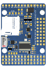
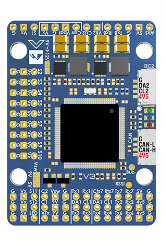
Description
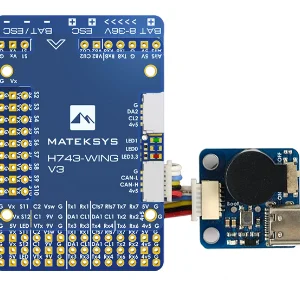
MATEKSYS H743-WING V3 FLIGHT CONTROLLER
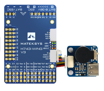
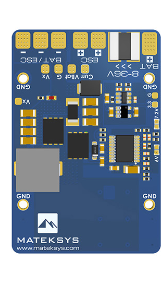
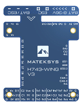
Matek’s H743 WING V3 Flight Controller arrives with new features and improvements over the V2 Version. This FC features a STM32H743VIT6 MCU running at 480MHz, dual gyros ICM42688-P(SPI1) & ICM42688-P(SPI4), a DPS310 (I2C2) barometer, and much more.
FC SPECIFICATION
- MCU: STM32H743VIT6, 480MHz , 1MB RAM, 2MB Flash
- IMU: ICM42688-P(SPI1) & ICM42688-P(SPI4)
- Baro: Infineon DPS310 (I2C2)
- OSD: AT7456E (SPI2)
- Blackbox: MicroSD card slot (SDIO)
- 7x Uarts (1,2,3,4,6,7,8) with built-in inversion.
- 13x PWM outputs(including “LED” pad)
- 2x I2C
- 1x CAN
- 6x ADC (VBAT, Current, RSSI, Analog AirSpeed, VB2, CU2)
- 3x LEDs for FC STATUS (Blue, Red) and 3.3V indicator(Red)
- 1x SPI3 breakout
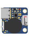
- USB/Beep Extender with Type-C(USB2.0)
- Dual Camera Inputs switch
- 5V/9V(12V) for Camera/VTX power switch
- High-precision Current Sense (90A continuous, 220A peak)
- Battery Voltage Sensor: 1K:10K (Scale 1100 in INAV, BATT_VOLT_MULT 11.0 in ArduPilot)
- ADC VB2 voltage divider: 1K:20K
- ADC AirSpeed voltage divider: 20K:20K
- Static power 160mA@5V
FC FIRMWARE
- ArduPilot(ChiBiOS): MATEKH743
- INAV: MATEKH743
PDB
- Input voltage range: 8~36V (3~8S LiPo) w/TVS protection
- 2x ESC power pads
- Current Senor: 220A, 3.3V ADC (Scale 150 in INAV, 66.7 A/V in ArduPilot)
- Sense resistor: 90A continuous, 220A peak.
BEC 5V OUTPUT
- Designed for Flight controller, Receiver, OSD, Camera, Buzzer, 2812 LED_Strip, Buzzer, GPS module, AirSpeed
- Output 5.15 +/- 0.1V DC
- Continuous current 2 Amps, 3A Peak
BEC 9V /12V OUTPUT
- Designed for Video Transmitter, Camera, Gimbal ect.
- Continuous current 2 Amps, 3A Peak
- 12V option with Jumper pad
BEC Vx OUTPUT
- Designed for Servos
- Voltage adjustable, 5V Default, 6V or 7.2V via jumper
- Continuous current 8 Amps, 10A Peak
BEC 3.3V OUTPUT
- Linear Regulator
- Continuous current: 200mA
PHYSICAL:
- Mounting: 30.5 x 30.5mm, Φ4mm with Grommets Φ3mm
- Dimensions: 54 x 36 x 13 mm
- Weight: 30g with USB extender
PACKAGE CONTENTS:
- 1x H743-WING v3
- 1x USB(Type-C)/Beep (Passive buzzer) Extender
- 1x 20cm JST-SH-6P to JST-SH-6P cable for USB extender.
- 2x 20cm JST-GH-4P to JST-GH-4P cable for CAN & I2C port
- 1x Rubycon ZLH 35V 470uF capacitor
- Dupont 2.54 pins (Board is shipped unsoldered)
INAV MAPPING
| INAV | |||||
| PWM | S1 | PB0 | 5 V tolerant I/O | TIM3_CH3 | Fixed Wing Motor |
| S2 | PB1 | 3.3 V tolerant I/O | TIM3_CH4 | ||
| S3 | PA0 | 5 V tolerant I/O | TIM5_CH1 | Fixed Wing Servo | |
| S4 | PA1 | 5 V tolerant I/O | TIM5_CH2 | ||
| S5 | PA2 | 5 V tolerant I/O | TIM5_CH3 | ||
| S6 | PA3 | 5 V tolerant I/O | TIM5_CH4 | ||
| S7 | PD12 | 5 V tolerant I/O | TIM4_CH1 | ||
| S8 | PD13 | 5 V tolerant I/O | TIM4_CH2 | ||
| S9 | PD14 | 5 V tolerant I/O | TIM4_CH3 | ||
| S10 | PD15 | 5 V tolerant I/O | TIM4_CH4 | ||
| S11 | PE5 | 5 V tolerant I/O | TIM15_CH1 | ||
| S12 | PE6 | 5 V tolerant I/O | TIM15_CH2 | ||
| LED | PA8 | 5 V tolerant I/O | TIM1_CH1 | 2812LED | |
| ADC | Vbat pad 1K:10K divider builtin | PC0 | 0~36V | Vbat ADC ADC_CHANNEL_1 | scale 1100 |
| Curr Pad | PC1 | 0~3.3V | Current ADC ADC_CHANNEL_2 | scale 150 | |
| RSSI Pad | PC5 | 0~3.3V | RSSI ADC ADC_CHANNEL_3 | Analog RSSI | |
| AirS Pad 20K:20K divider builtin | PC4 | 0~6.6V | AirS ADC ADC_CHANNEL_4 | Analog Airspeed | |
| VB2 Pad 1K:20K divider builtin | PA4 | 0~69V | ADC_CHANNEL_5 | scale 2100 | |
| CU2 Pad | PA7 | 0~3.3V | ADC_CHANNEL_6 | spare | |
| I2C | I2C1 CL1/DA1 | PB6/PB7 | 5 V tolerant I/O | Compass | QMC5883 / HMC5883 IST8310 / IST8308 MAG3110 / LIS3MDL |
| OLED | 0.96″ | ||||
| I2C2 CL2/DA2 on JST-GH-4P | PB10/PB11 | 5 V tolerant I/O | onboard Barometer | DPS310 | |
| Digital Airspeed sensor | MS4525 | ||||
| Temperature sensor | |||||
| UART | USB | PA11/PA12 | 5 V tolerant I/O | USB | |
| TX1 RX1 | PA9/PA10 | 5 V tolerant I/O | USART1 | telem2 | |
| TX2 RX2 | PD5/PD6 | 5 V tolerant I/O | USART2 | GPS1 | |
| TX3 RX3 | PD8/PD9 | 5 V tolerant I/O | USART3 | GPS2 | |
| TX4 RX4 | PB9/PB8 | 5 V tolerant I/O | UART4 | USER | |
| TX6 RX6 | PC6/PC7 | 5 V tolerant I/O | TX6 & RX6 | CRSF | |
| UART6_RX | SBUS/IBUS/DSM/PPM | ||||
| UART6_TX | FPORT/SRXL2 | ||||
| RX7 TX7 | PE7/PE8 | 3.3 V tolerant I/O | UART7 | telem1 | |
| TX8 RX8 | PE1/PE0 | 5 V tolerant I/O | UART8 | USER | |
ARDUPILOT MAPPING
| ArduPilot | ||||||
| PWM | S1 | PB0 | 5 V tolerant I/O | PWM1 GPIO50 | TIM8_CH2N | Group1 |
| S2 | PB1 | 3.3 V tolerant I/O | PWM2 GPIO51 | TIM8_CH3N | ||
| S3 | PA0 | 5 V tolerant I/O | PWM3 GPIO52 | TIM5_CH1 | Group2 | |
| S4 | PA1 | 5 V tolerant I/O | PWM4 GPIO53 | TIM5_CH2 | ||
| S5 | PA2 | 5 V tolerant I/O | PWM5 GPIO54 | TIM5_CH3 | ||
| S6 | PA3 | 5 V tolerant I/O | PWM6 GPIO55 | TIM5_CH4 | ||
| S7 | PD12 | 5 V tolerant I/O | PWM7 GPIO56 | TIM4_CH1 | Gourp3 | |
| S8 | PD13 | 5 V tolerant I/O | PWM8 GPIO57 | TIM4_CH2 | ||
| S9 | PD14 | 5 V tolerant I/O | PWM9 GPIO58 | TIM4_CH3 | ||
| S10 | PD15 | 5 V tolerant I/O | PWM10 GPIO59 | TIM4_CH4 | ||
| S11 | PE5 | 5 V tolerant I/O | PWM11 GPIO60 | TIM15_CH1 | Group4 | |
| S12 | PE6 | 5 V tolerant I/O | PWM12 GPIO61 | TIM15_CH2 | ||
| LED | PA8 | 5 V tolerant I/O | PWM13 GPIO62 | TIM1_CH1 | Group5 | |
| SERVO13_FUNCTION 120, NTF_LED_TYPES neopixel | ||||||
| PWM1~PWM13 are Dshot and PWM capable. However, mixing Dshot and normal PWM operation for outputs is restricted into groups, ie. enabling Dshot for an output in a group requires that ALL outputs in that group be configured and used as Dshot, rather than PWM outputs. If servo and motor are mixed in same group, make sure this group run lowest PWM frequency according to the servo specification. ie. Servo supports Max. 50Hz, ESC must run at 50Hz in this group. | ||||||
| ADC | Vbat pad 1K:10K divider builtin | PC0 | 0~36V | Vbat ADC onboard battery voltage sense | BATT_VOLT_PIN BATT_VOLT_MULT | 10 11.0 |
| Curr pad | PC1 | 0~3.3V | Current ADC onboard current sense | BATT_CURR_PIN BATT_AMP_PERVLT | 11 66.7 | |
| VB2 Pad 1K:20K divider builtin | PA4 | 0~69V | Vbat2 ADC | BATT2_VOLT_PIN BATT2_VOLT_MULT | 18 21.0 | |
| CU2 Pad | PA7 | 0~3.3V | Current2 ADC | BATT2_CURR_PIN BATT2_AMP_PERVLT | 7 / | |
| RSSI Pad | PC5 | 0~3.3V | RSSI ADC Analog RSSI | RSSI_ANA_PIN RSSI_TYPE | 8 1 | |
| AirS Pad 20K:20K divider builtin | PC4 | 0~6.6V | AirS ADC Analog Airspeed | ARSPD_PIN ARSPD_TYPE | 4 2 | |
| I2C | I2C1 CL1/DA1 | PB6/PB7 | 5 V tolerant I/O | Compass | COMPASS_AUTODEC | 1 |
| I2C2 CL2/DA2 on JST-GH-4P | PB10/PB11 | 5 V tolerant I/O | on board Baro DPS310 | Address | 0x76 | |
| Digital Airspeed I2C MS4525 DLVR-L10D | ARSPD_BUS ARSPD_TYPE ARSPD_TYPE | 0 1 9 | ||||
| CAN | CAN1 | PD0/PD1 | 5 V tolerant I/O | CAN Node | CAN_D1_PROTOCOL CAN_P1_DRIVER | 1 1 |
| CAN GPS CAN Compass CAN Airspeed sensor | GPS_TYPE COMPASS_TYPEMASK ARSPD_TYPE | 9 0 8 | ||||
| UART | USB | PA11/PA12 | 5 V tolerant I/O | USB | console | SERIAL0 |
| RX7 TX7 RTS7 CTS7 | PE7/8/9/10 | 3.3 V tolerant I/O | UART7 | telem1 | SERIAL1 | |
| TX1 RX1 | PA9/PA10 | 5 V tolerant I/O | USART1 | telem2 | SERIAL2 | |
| TX2 RX2 | PD5/PD6 | 5 V tolerant I/O | USART2 | GPS1 | SERIAL3 | |
| TX3 RX3 | PD8/PD9 | 5 V tolerant I/O | USART3 | GPS2 | SERIAL4 | |
| TX8 RX8 | PE1/PE0 | 5 V tolerant I/O | UART8 | USER | SERIAL5 | |
| TX4 RX4 | PB9/PB8 | 5 V tolerant I/O | UART4 | USER | SERIAL6 | |
| TX6 RX6 | PC6/PC7 | 5 V tolerant I/O | USART6 | RC input/Receiver | SERIAL7 | |
| RX6 | SBUS/IBUS/DSM/PPM | |||||
| TX6 | FPORT/SRXL2 | |||||
RC INPUT
The Rx6 pin, which by default is mapped to a timer input, can be used for all ArduPilot supported receiver protocols, except CRSF which requires a true UART connection. However, bi-directional protocols which include telemetry, such as SRXL2 and FPort, when connected in this manner, will only provide RC without telemetry.
To allow CRSF and embedded telemetry available in Fport, CRSF, and SRXL2 receivers, the Rx6 pin can also be configured to be used as true UART RX pin for use with bi-directional systems by setting the BRD_ALT_CONFIG to “1” so it becomes the SERIAL7 port’s RX input pin.
With this option, SERIAL7_PROTOCOL must be set to “23”, and:
- PPM is not supported.
- SBUS/DSM/SRXL connects to the Rx6 pin, but SBUS requires that the SERIAL7_OPTIONS be set to “3”.
- FPort requires connection to Tx6 and SERIAL7_OPTIONS be set to “7”. If Telemetry doesn’t work, try set SERIAL7_OPTIONS = 135.
- CRSF also requires a Tx6 connection, in addition to Rx6, and automatically provides telemetry. Set SERIAL7_OPTIONS to “0”.
- SRXL2 requires a connection to Tx6 and automatically provides telemetry. Set SERIAL7_OPTIONS to “4”.
Any UART can be used for RC system connections in ArduPilot also, and is compatible with all protocols except PPM. See Radio Control Systems for details.
–
ArduPilot Relay(PINIO)
- Camera-1 and Vsw On by default
- Make sure 2 cameras are set with identical video format, both PAL or both NTSC.
# GPIOs
- PD10 PINIO1 OUTPUT GPIO(81) //Vsw pad power switch
- PD11 PINIO2 OUTPUT GPIO(82) //Camera switch
# RCx_OPTION: RC input option
- 28 Relay On/Off
- 34 Relay2 On/Off
- 35 Relay3 On/Off
- 36 Relay4 On/Off
e.g.
- RELAY_PIN 81 //Vsw GPIO
- RC7_OPTION 28 //Relay On/Off, Use CH7 of Transmitter to switch Vsw
- RELAY_PIN2 82 //Camera switch GPIO
- RC8_OPTION 34 //Relay2 On/Off, Use CH8 of Transmitter to switch camera
or
- RELAY_PIN3 81 //Vsw GPIO
- RC9_OPTION 35 //Relay3 On/Off, Use CH9 of Transmitter to switch Vsw
- RELAY_PIN4 82 //Camera switch GPIO
- RC10_OPTION 36 //Relay4 On/Off, Use CH10 of Transmitter to switch camera
The configured feature will be triggered when the auxiliary switch’s pwm value becomes higher than 1800. It will be deactivated when the value falls below 1200.
Check the pwm value sent from the transmitter when the switch is high and low using the Mission Planner’s Initial Setup >> Mandatory Hardware >> Radio Calibration screen. If it does not climb higher than 1800 or lower than 1200, it is best to adjust the servo end points in the transmitter.
TIPS & NOTES
| H743-WING | ArduPilot | INAV | ||
| V1 Blue PCB | ICM20602(1st) MPU6000(2nd) | ArduPilot 4.0 stable or newer | MPU6000 (0) default ICM20602 (1) | INAV 3.0 or newer |
| V2 Purple PCB | ICM42605(1st) MPU6000(2nd) | ArduPilot 4.1 stable or newer | MPU6000 (0) default ICM42605 (2) | INAV 4.0 or newer |
| V3 Blue PCB | ICM42688P(1st) ICM42688P(2nd) | ArduPilot plane 4.2.0 stable or newer | ICM42688P (0) default ICM42688P(2) | INAV 5.0 or newer |
*** V1/V2/V3 share same ArduPilot/INAV Target ***
ArduPilot
- Current sensor range is 220A on H743-WING-V2/V3, make sure you set the BATT_AMP_PERVLT to 66.7
- with ArduPilot 4.1 or higher, set INS_ENABLE_MASK to 7 or default 127.
- Pls download “plane 4.2.0 or newer” ArduPilot firmware for H743-WING-V3
- It is recommended to use STM32CubeProgrammer to erase MCU and upload firmware. check this blog http://www.mateksys.com/?p=6905
INAV
- Current sensor range is 220A on H743-WING-V2/V3, make sure you set the Current Meter Scale to 150
- H743-WING-V3 is not supported by INAV4.1 downloaded from configurator. pls download inav_4.1.0_MATEKH743_42688 from our website.
- Starting with INAV5.0, they will share the same firmware.
Others
- If the ESCs you are using don’t have enough capacitors integrated, low ESR electrolytic capacitor is required for reducing ESC noise.
Reviews
There are no reviews yet.