
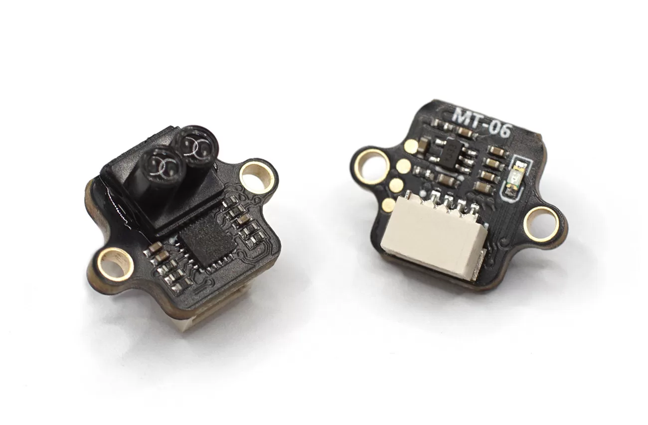
Specifications
- Interface Mode: UART(115200); I2C;
- Protocol: Micolink/ Mavlink(Default)/ MSP/ I2C/ I2C_NOOPLOOP
- Output Rate: 50Hz
- Firmware Supported: Ardupilot/PX4/INAV/FMT
- TOF Range: 6m@90% reflectance/10KLux;
- Center Wavelength: 940nm
- Dead Zone: 2cm
- Ranging Accuracy: 4cm(<2m@90% reflectance); 1.5%(>2m@90% reflectance)
- Power Consumption: 100mW
- Supply voltage: 5V
IIC Protocol
The MT-06 can be switched to I2C mode using MicoAssistant and supports two I2C protocols: one is customized by MicoAir, and the other is the NOOPLOOP protocol, which is directly supported by ArduPilot (RNGFNDx_TYPE=40).
Important: The module does not have built-in pull-up resistors. For the I2C to work properly, external pull-up resistors are necessary.
FAQ: “When the module is in I2C mode, how could I connect it to MicoAssistant to change it back to UART mode?”
When the module is switched to I2C mode, it will no longer be able to communicate and configure it normally via the serial port. Special steps are required to re-establish communication.
- Connect your USB-TTL module to your computer. Do not connect the sensor to it yet.
- Open the MicoAssistant software. Find the correct port for your USB-TTL module, set the baud rate to 115200, and click “Connect.”
- While MicoAssistant remains connected to the port, plug the MT-06 module into the USB-TTL module. At this point, MicoAssistant should correctly recognize the module information.
- If you experience device refresh/port disconnection issues when connecting the sensor to the TTL module, adding a large capacitor in parallel with the TTL module’s 5V output might resolve the problem.
IIC (MicoAir)
In this mode, the module’s 7-bit I2C address is 0x32 + ID. The ID defaults to 0 and can be set from 0 to 0x1F, giving the module an I2C address range of 0x32 to (0x32 + 0x1F).
You can use MicoAssistant to modify the module ID to different values, allowing the flight controller to connect to multiple MT-06 modules simultaneously.
IIC_NOOPLOOP
In this mode, the module’s 7-bit I2C address is 0x08 + ID. The ID defaults to 0 and can be set from 0 to 0x1F, giving the module an I2C address range of 0x08 to (0x08 + 0x1F).
In Ardupilot, you should set:
- RNGFNDx_ADDR=8 (default address)
- RNGFNDx_ORIENT = (The same as the module, default value is 25/DOWN)
- RNGFNDx_TYPE = 40
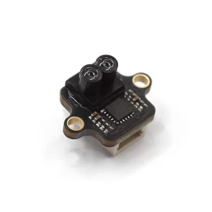
Physical
- Dimensions: 16 x 12 x 10mm
- Weight: 0.8g
In IIC Mode:
- Rx = SDA
- Tx = SCL
Reviews
There are no reviews yet.